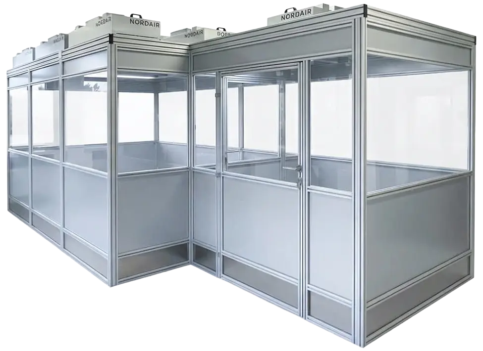
At Nordair Systems, the layout of the cleanroom cabin is completely variable. Since the products are based on aluminum profiles, they are not bound to rigid grid dimensions. Nordair Systems creates L-shapes, U-shapes or recesses for hall columns to integrate the cabin into your existing production environment and material flow.
Freedom vs Grid
In technical reality, production halls are rarely empty. There are support columns, cable lines, ventilation ducts or existing machines. A rigid grid fails here. Nordair Systems uses a more flexible model: Since our aluminum profiles are cut to size, we are not bound to fixed grids. We design the cabin geometry exactly around existing interfering contours.
Designed for complex floor plans
The layout of a cleanroom cabin must follow the value stream, not the other way around. If your material flow requires an L-shape or U-shape to convert a machine, we adjust the cabin statics accordingly.