Introduction
The air exchange rate (LWR), also known as air changes per hour, ACH for short, is one of the central parameters when designing a clean room or a clean process zone. It indicates how often the entire air volume of a room is replaced by filtered air per hour. If you plan too few air changes, you risk particulate accumulation and quality problems. If you plan too much, you pay unnecessarily high operating costs over the long term, not linearly, but exponentially.
This article shows which guidelines actually apply to which ISO class, why many of the figures circulating on the Internet are neither normative nor empirically reliable, and how you can actually calculate the required air flow for your system.
What is the air exchange rate and how do you calculate it?
The air exchange rate describes the ratio between the filtered air volume supplied every hour and the volume of the room:
ACH = Filtered air volume per hour (m³/h) ÷ room volume (m³)
Example: A room with a volume of 56 m³, to which 2,240 m³ of filtered air per hour is supplied, has an air exchange rate of 40 ACH. This is in line with the planning guideline for ISO 7.
The challenge lies in finding the right target size: What ACH number is actually required for your ISO class, and how do you achieve it with the right hardware?
Air exchange rate according to ISO class: overview of indicative values
A common misconception: Many sources on the Internet, including AI-generated answers, cite ACH guidelines and attribute them to DIN EN ISO 14644-1. In fact, ISO 14644-1 only defines particle concentration limits per purity class. The standard does not contain ACH requirements. What is circulating on the Internet as “ISO indicative values” are partly outdated planning recommendations from secondary sources, partly unaudited disseminated figures, often significantly oversized.
ISO 14644-1 defines purity classes exclusively based on the maximum allowable particle concentration. For example, ISO 7 allows a maximum of 352,000 particles ≥ 0.5 µm per cubic meter of air. The ACH number required to reach this limit is not a constant. It depends on the specific particle generation rate in the room. A highly automated ISO 7 clean room without human presence requires a fraction of the air exchange rate of the same room with five workers when assembled manually.
At Nordair Systems, we have empirically validated the actual required air exchange rates over hundreds of project designs. The result is a simple, robust model: Each ISO level doubles the air exchange requirement.
Note: Certification is based on proof of the actual particle concentration in accordance with DIN EN ISO 14644-1:2015, not the ACH number. The air exchange rate is a design parameter, not a certification value. The “Frequently cited” column shows the bandwidths that are most frequently mentioned in German-language Internet sources and AI-generated answers. The established international planning references (ASHRAE Design Guide for Cleanrooms, Whyte 2011) are in some cases significantly lower. This confirms the finding that the values disseminated online come from the most conservative GMP context and were adopted without source verification.
The VDI Guideline 2083 Part 1, which is applicable in Germany, completely adopts the ISO classification and supplements it with aspects such as energy efficiency and industry-specific information for microelectronics and photonics. VDI 2083 Part 19 (Tightness of clean rooms) is also relevant for calculating the excess air required to maintain the differential pressure: The denser the building, the less excess air the ventilation system must deliver.
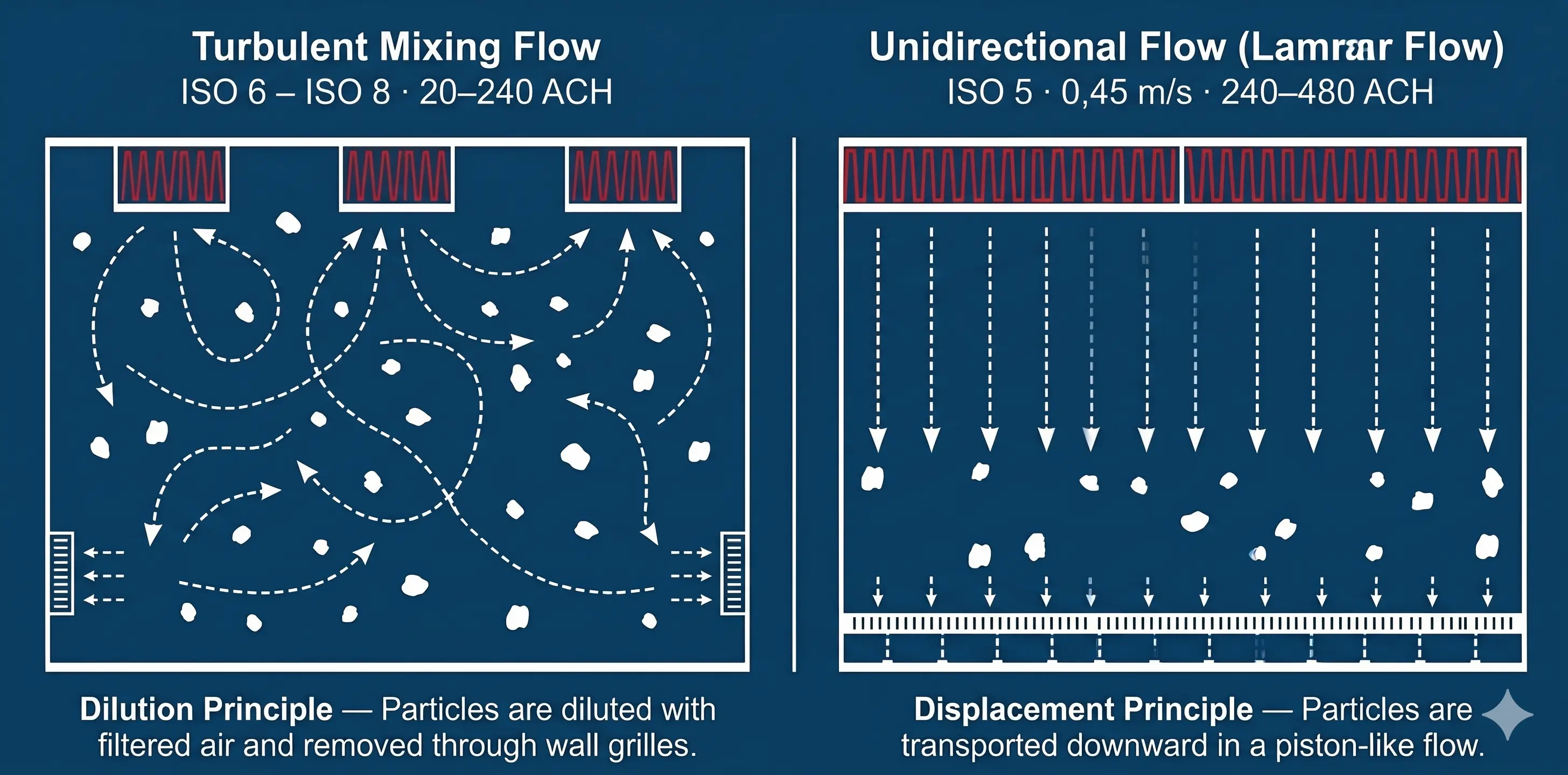
Laminar flow: When air velocity is more important than ACH
With ISO 5 and below, the ACH number becomes largely irrelevant as a planning variable. The flow rate is decisive.
Unidirectional flow (laminar flow) works on a fundamentally different principle than turbulent mixed ventilation: The filtered air flows downwards from the HEPA filter surface in a uniform, parallel flow and removes particles directly from the working area instead of just diluting them. The entire ceiling area (or wall area in case of horizontal flow) must be covered with particulate filters, typically with a filter coverage level of over 80%. The air descends across the working area as a homogeneous, parallel piston and captures emitted particles in the shortest geometric path, without lateral backmixing.
The target value: According to DIN EN ISO 14644-3, the recommended air velocity for unidirectional flow is 0.45 m/s ± 20%, measured 150 to 300 mm below the filter outlet surface. This corresponds to a range of 0.36 to 0.54 m/s. The EU GMP Guide Annex 1 (2022) confirms this guideline for open cleanroom applications.
Important for practice: ISO 14644-3 measures the flow rate directly below the filter (150 to 300 mm distance from the filter surface, measurement using a calibrated hot wire or impeller anemometer in a defined grid). The EU-GMP Annex 1 requires the same working height value. Since the air jet slows down slightly as a result of shear friction with the ambient air, the outlet speed at the filter must be set marginally higher when the room height is higher in order to reach 0.45 m/s at working height.
Why exactly 0.45 m/s? The value, derived historically from NASA specifications of the 1960s (90 feet per minute), is an experimentally determined compromise between two physical borderline cases:
- Too slow (< 0.36 m/s): Every heat source in a clean room, whether human body (~100 W sensitive heat output) or operating medium, produces an upward convective flow (thermal plume). If the downward flow is too weak, it is penetrated by these thermal plumes. Particles stagnate or rise into the work zone against gravity.
- Too fast (> 0.54 m/s): If the flow hits an obstacle (work table, robotic component, operator's head), the flow is separated at the inflow edge. If the number of Reynolds is too high, backflow areas with vortex releases and local backflows arise on the Lee-side. These microturbulences trap contaminants instead of transporting them away.
0.45 m/s is exactly the sweet spot where the flow reliably overcomes thermal plumes without creating destructive vortices on obstacles.
Consequence for interpretation: Who a Laminar Flow Box or a cleanroom cabins-Configuration for ISO 5 plans, specifies filter coverage area and FFU performance based on target speed, not on the basis of an ACH number. The high air exchange rates (160+ ACH) are then calculated as a result of laminar flow, not vice versa. Anyone who sizes a laminar flow zone based on a fictitious ACH number is making a methodological mistake.
Factors influencing the air exchange rate
The indicative values in the table are starting points, not absolute values. Three factors determine whether the theoretical ACH number is sufficient in practice:
Staffing and processes
Humans are the biggest source of particles in a clean room. The physiological process of desquamation, the continuous shedding of dead skin cells from the stratum corneum, releases particles continuously. These skin flakes, often populated with microorganisms, act as carriers for contamination (so-called microbe carrying particles).
Kinetic dispersion, i.e. the release of particles as a function of body movement, was comprehensively quantified in William Whyte's canonical dispersion models:
Data source: Whyte, W. (2011). Cleanroom Technology: Fundamentals of Design, Testing and Operation (2nd ed.). Wiley & Sons
In practice, this means: For a single workstation in an ISO 7 zone, 40 ACH is usually sufficient. If the occupancy rises to five employees handling components, the particle generation rate increases by a factor of ten. The planning value must be adjusted upwards accordingly. The concentration of contaminants in the room is directly proportional to the generation rate and inversely proportional to the volume of incoming air. A room that is stubbornly dimensioned according to the table and ignores kinetic particle dispersion will get out of hand during operation.
differential pressure
Clean rooms are operated at a slight excess pressure compared to the environment (typically at least 10 Pa opposite the adjacent area). This excess pressure prevents uncontrolled air from entering through joints or openings. ISO 14644-4 recommends 5 to 15 Pa, the stricter EU-GMP Annex 1 mandates 10 to 15 Pa between adjacent areas of different purity classes. In practice, critical zones are often driven at even higher pressures (e.g. 21 Pa) in order to build up a safety buffer against transient disturbances such as the abrupt opening of lock doors and the gradual pressure drop caused by clogging filters.
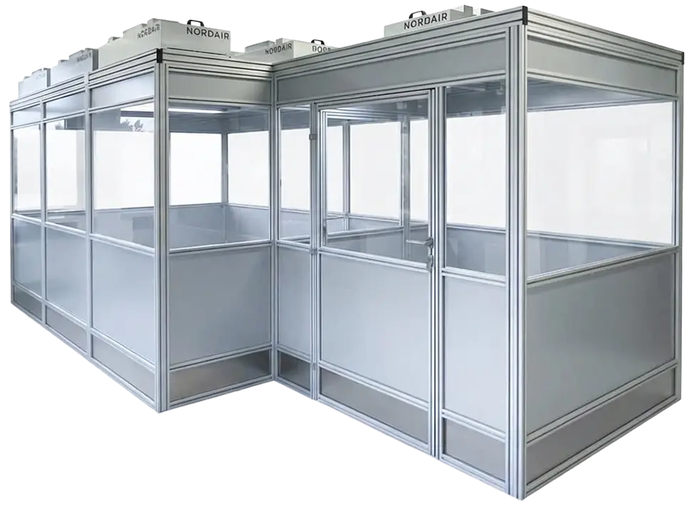
One cleanroom cabin from Nordair Systems is designed as an overpressure system: The filter fan units permanently pump more filtered air into the cabin than can escape through leaks. The permanent excess flow (Make-up Air) required for overpressure must be integrated into the ACH calculation.
The pressure cascade (cleanest zone with highest pressure, adjacent lock with medium pressure, environment with ambient pressure) is a decisive planning feature that is directly related to the ACH design. The denser the building is designed in accordance with VDI 2083 Part 19 (tightness of clean rooms), the less excess air must be pumped by the ventilation system.
GMP requirements
Anyone who produces drugs or medical devices is subject to the EU GMP guidelines with classes A to D. These classes correlate with ISO classes (e.g. Grade A ≈ ISO 5) but define massive additional requirements: microbiological limits, continuous viable monitoring, a holistic Contamination Control Strategy (CCS) in accordance with the 2022 revised version of Annex 1. This effort is mandatory for pharmaceutical sterile production, for industrial applications in photonics, precision engineering or metal processing However, neither normatively required nor economically viable.
It should be clearly stated at this point: Nordair Systems does not specialize in GMP requirements. For our photonics, precision engineering or metalworking customers, ISO 14644 and VDI 2083 are the decisive framework. The oversized ACH values that circulate on the Internet often come from exactly this GMP context and are mistakenly transferred to industrial applications where inert particles count as a physical disturbance factor, not microbiological replication.
Practical example: Calculate air exchange rate and translate it to hardware
Let's say you're planning a clean island for component handling and packaging after the cleaning plant. Target class ISO 7:
Step 1: Determine room volume
- Area: 5 m × 4 m = 20 m²
- Room height: 2.8 m
- Volume: 20 m² × 2.8 m = 56 m³
Step 2: Set target ACH
- ISO 7 practice guideline (Nordair, empirically validated): 40 OH
- For a workplace with 2 people and moderate activity, this value is sufficient. In the case of higher staffing levels or particle-intensive processes, an upward adjustment is made.
Step 3: Calculate required airflow
- Air flow = 56 m³ × 40 ACH = 2,240 m³/h
Step 4: Derive hardware
- A Nordair systems cleanroom cabin With suitably designed filter fan units, this throughput provides the required filter coverage for ISO 7.
- The exact FFU configuration depends on room geometry, filter coverage, return air flow and the excess flow required for the differential pressure. This is determined in the design consultation.
The key point: The calculation is not complex. The errors usually arise not with the formula, but with the assumption of the boundary conditions. Incorrect staffing, lack of differential pressure buffer, underestimated process particles. Or even oversized guidelines that have been adopted from the wrong context and unnecessarily multiply the plant's energy requirements.

Figure: One cleanroom cabin by Nordair Systems
What air exchange rate does a lock or changing room need?
Locks and changing rooms are not clean rooms, but critical transition zones. Your task is to minimize the transfer of particles from the environment into the clean room.
As a guideline, locks and changing rooms are typically 10 to 20 ACH (ISO 8 level). This corresponds to the lowest end of the cleanroom classification, but a multiple of the ACH rate of normal office or production ventilation.
Why is this comparatively low value sufficient even though the dressing is extremely particle-intensive? The answer lies in the geometric volume and recovery time: Since locks usually have a small volume of space, 20 ACH generate a rapid exchange of air. The recovery time, i.e. the time required for the system to reduce the particle concentration by a factor of 100 after a brief spike in contamination (e.g. by opening a door or changing room), remains short enough not to compromise the clean room.
The pressure hierarchy is decisive here: The clean room has the highest overpressure, the changing room has a medium overpressure compared to the environment. Air always flows from clean to less clean. Never the other way around. This cascading structure guarantees the protection against infiltration required by ISO 14644-4, regardless of whether the door to the lock has just been opened or not.
Conclusion: Air exchange rate is a design parameter, not a certification value
The common confusion: Many believe that reaching a specific ACH number means meeting an ISO class. That is not true. The ISO class is proven by counting particles, not by measuring the air exchange rate.
Just as common: The assumption that the ACH areas circulating on the Internet originate from ISO 14644-1. That is not the case. The standard defines particle limits. The ACH values, which are falsely attributed to it, come from GMP-oriented planning guidelines and were disseminated via secondary sources and AI-generated content as supposed standard values. With real consequences: oversized systems, quadrupled energy costs and clean room concepts that move more air than the process requires.
The ACH number is the tool for reliably reaching and maintaining the particle class in practice. Anyone who plans with validated guidelines and realistically estimates the influencing factors (staffing, process particles, differential pressure) builds a system that works in operation. Without overengineering.
Unsure what air exchange rate your process requires? We help with the design, specifically and without overengineering.
Source citations
- DIN EN ISO 14644-1:2015. clean rooms and associated clean room areas. Part 1: Classification of air purity based on particulate concentration Beuth Verlag, Berlin. (Defines particle limits per ISO class; does not include ACH guidelines.)
- DIN EN ISO 14644-3:2019. clean rooms and associated clean room areas. Part 3: Test methods. Beuth Verlag, Berlin. (Includes guideline value 0.45 m/s ± 20% for unidirectional flow, measured 150 to 300 mm below filter surface.)
- DIN EN ISO 14644-4:2022. clean rooms and associated clean room areas. Part 4: Planning, construction and initial operation. Beuth Verlag, Berlin. (Recommends 5 to 15 Pa differential pressure between cleanroom zones.)
- Whyte, W. (2011). Cleanroom Technology: Fundamentals of Design, Testing and Operation (2nd ed.). Wiley & Sons (Standard reference for design calculations, particle emission models, and kinetic dispersion data.)
- VDI 2083 Part 1. Clean room technology: Air particle purity classes. Association of German Engineers, Düsseldorf. (National supplement to ISO 14644-1 with industry-specific notes for microelectronics and photonics.)
- VDI 2083 Part 19. Cleanroom Technology: Tightness of clean rooms. Association of German Engineers, Düsseldorf. (Defines leak classes 0 to 7 for calculating the required excess flow rate.)
- European Commission, EU GMP Guide Annex 1 (2022): Manufacturing of sterile medicinal products. European Medicines Agency, Amsterdam. (Guideline value 0.36 to 0.54 m/s at working height for grade A zones; requires 10 to 15 Pa differential pressure.)
.webp)